|
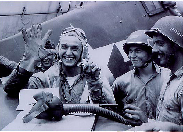
(Then) LTJG Alex S.Vraciu after he claimed 6 "Judy" dive bomber kills in 8 minutes during the Marianas Turkey Shoot on 19 June 1944 earning him the Navy Cross |
|
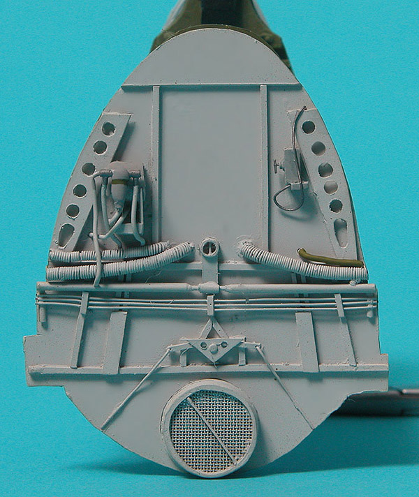
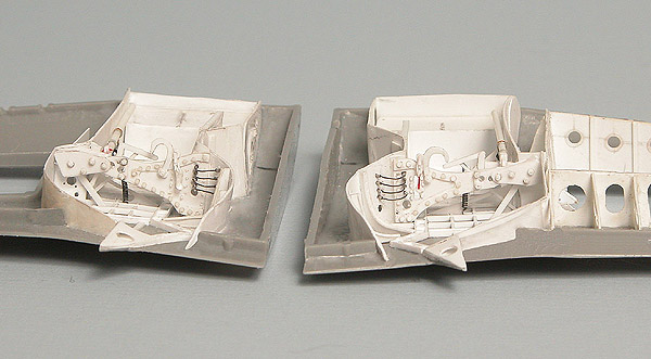
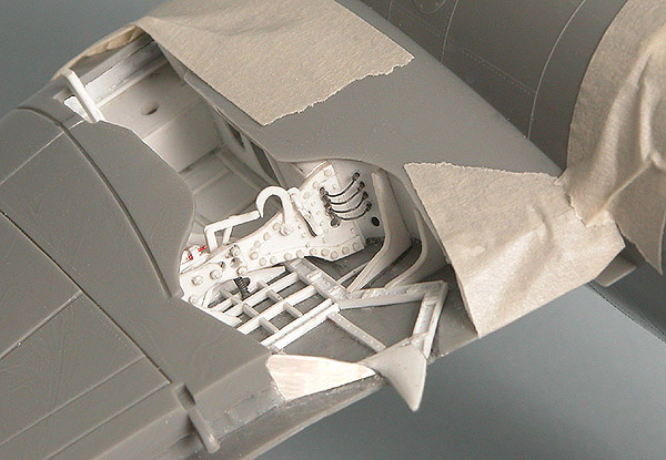
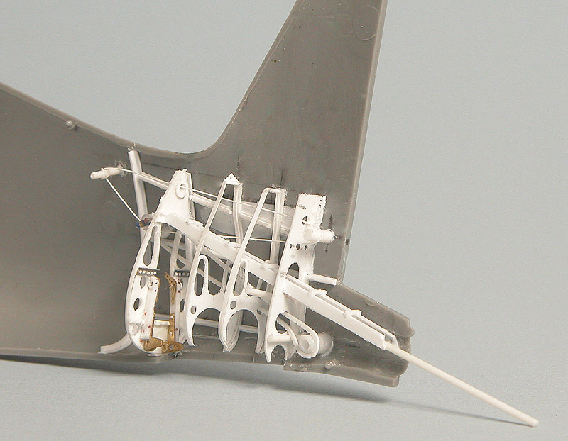
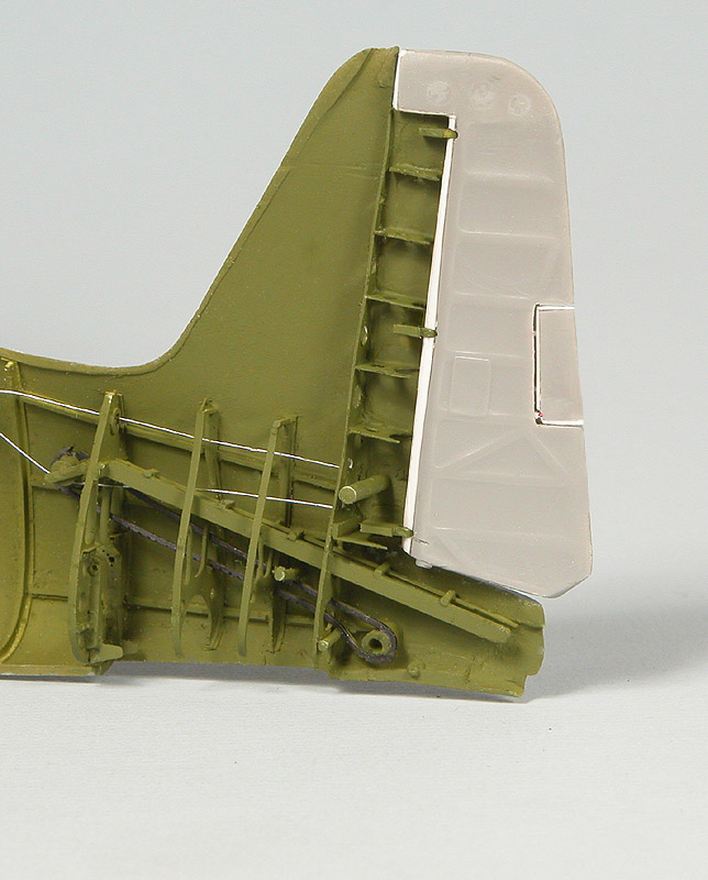
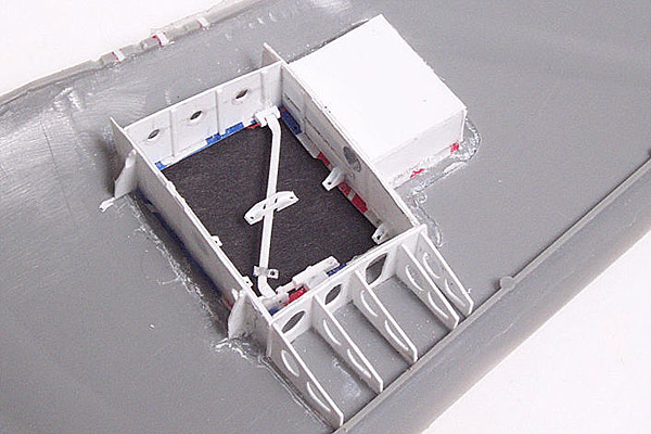
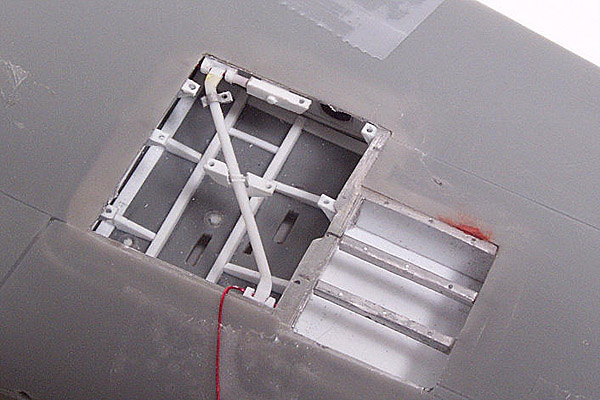
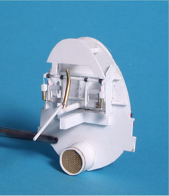
| Port .50 gun bay | |
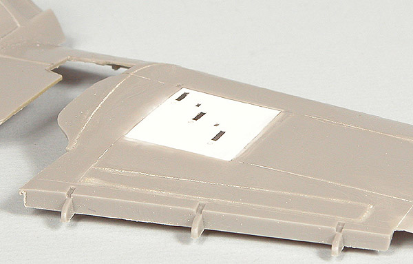
| Just as I did
with the Revell 1/32 P-47D I completely rebuilt, I started with the port
.50 cal installation (superstitious I guess). Hasegawa provided for a kit
gun installation but it was woefully inadequate. First order of business
was to fill in the horrendous recessed panel lines with CA. New ones will
need to be scribed in. I also cut out the area for the ammo cans. Soda can
aluminum was cut out, in one piece, to make the "lip" that goes around the
opening. Much more work is going to be needed around this area that the
Jug. The plastic was thinned significantly from behind using a Dremel
cutting bit to give a more scale effect.
|
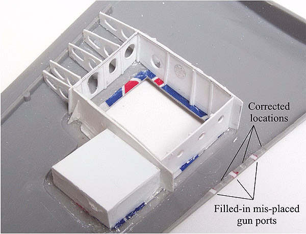 |
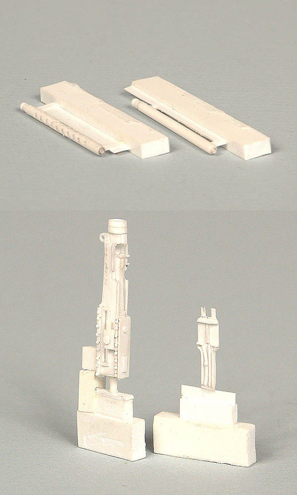
| The basic bulkhead and rib work is done but a lot of work still remains. Hasegawa got the location of the spend shell ejection chutes correct per the Grumman drawings but misaligned the gun ports. They were filled in and moved to the correct location. All the small details have been added. The stiffening bar on the real thing is hinged and swings forward to allow access to the guns. I used a 0.010" piece of wire to make the pin that holds it, it mine swing freely to allow me to install the guns when the time comes. The doors were made from soda can aluminum with styrene details added. The only details left are the ammo boxes, ammo and putting together 3 resin guns. I did the masters for the guns and each has a separate feed tray cover, I will leave at least one of them open . | |
  |
|
|
|
|
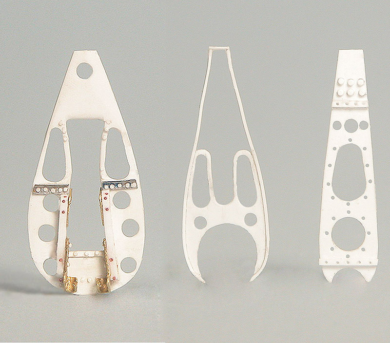
| The Cockpit | |
|
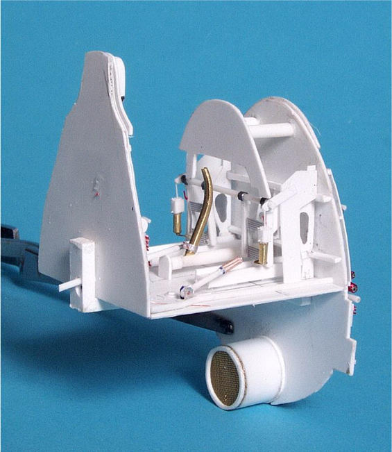
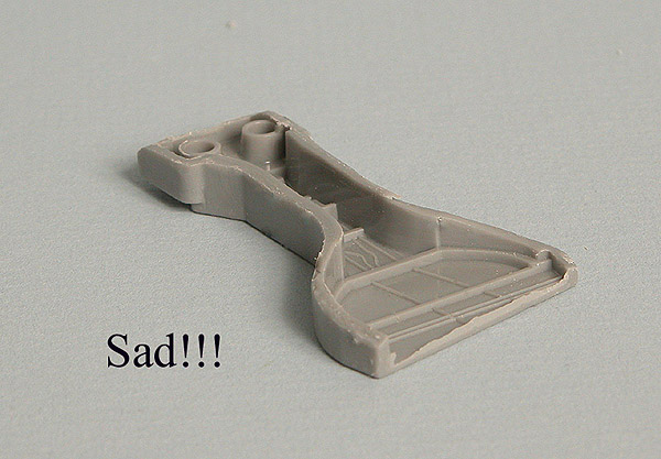
What is there to say about the kit cockpit besides that it belongs only in
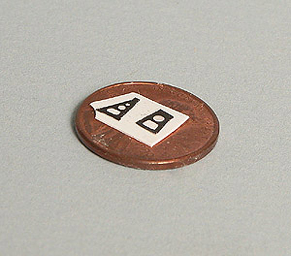
the trash. It is very primitive and very generic in details. Waldron makes
an outstanding cockpit placard set and I will use their instruments and
seatbelt hardware to complement the scratch building. Once I started
comparing the kit pieces to the drawings it became immediately apparent
that the kit floor was about 7mm too high. This necessitated chucking the
rear bulkhead for use as a template. Instead I used the contour gauge to
make a new rear bulkhead and firewall.
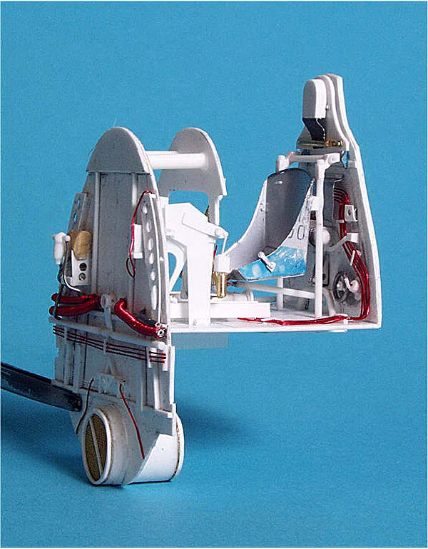
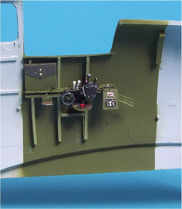
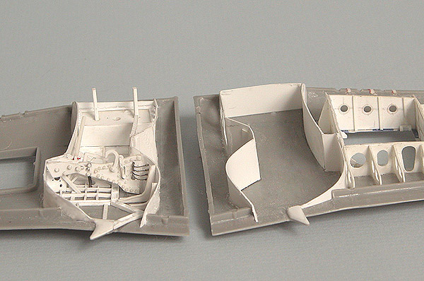
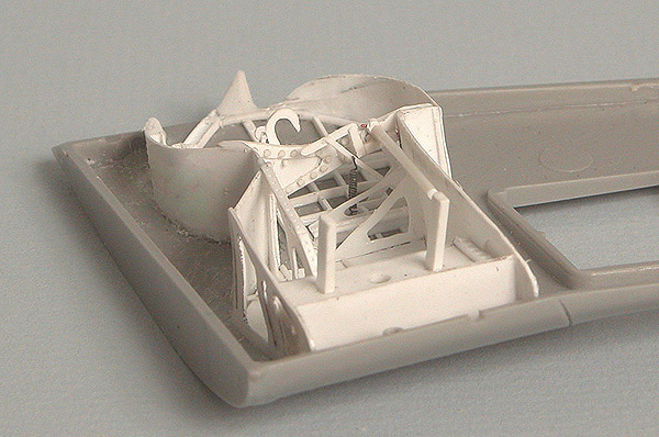
The floor and rear bulkhead were cut from sheet styrene, as was the instrument panel bulkhead (the actual panel itself will be attached to this bulkhead). The attachment brackets for the rudder pedals are now in shape, as are other bulkhead details. The two cross stiffeners were shaped from styrene "I" beam. The Hellcat had a floor, unlike the Corsair and Wildcat, and foot troughs attached to the floor. The troughs were cut from a piece of styrene I-beam. Some small pieces of styrene strip were used for spacers underneath. The rudder pedals were scratch built from styrene, brass and steel. The stick was made from brass rod and both the stick and the elevator connecting rod actually pivot. This is more to make installation in the cockpit once it is ready to be put together but it was also fun to just make it articulate! I will most likely leave it loose once the cockpit is together. The emergency hydraulic hand pump handle on the right side of the cockpit floor (below) also pivots, again to make it easier to position once the cockpit is together.
|
|
  |
|
|
|
|
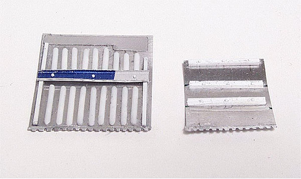
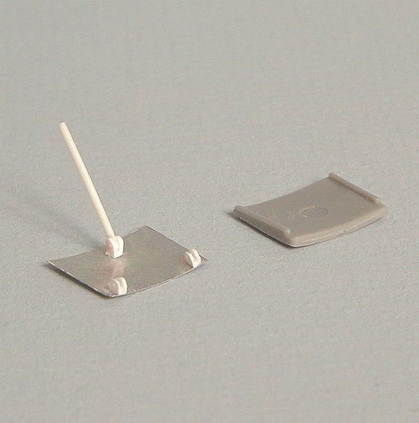
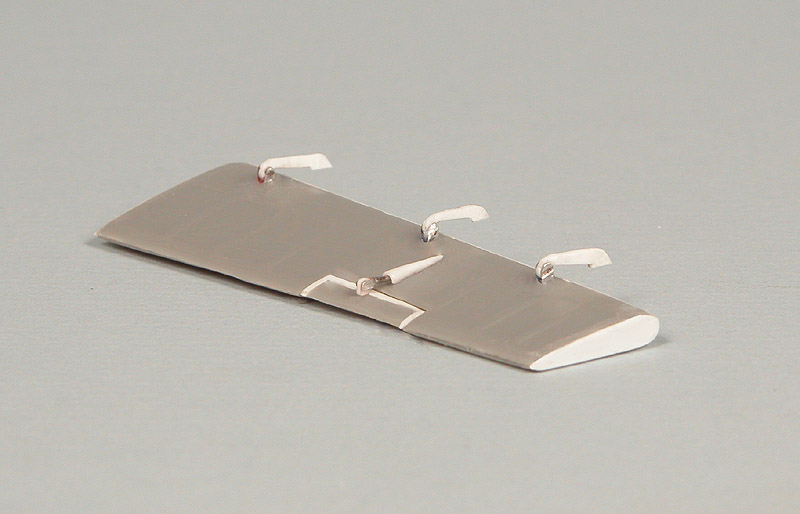
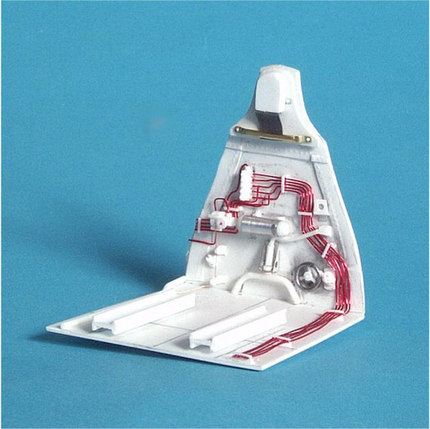
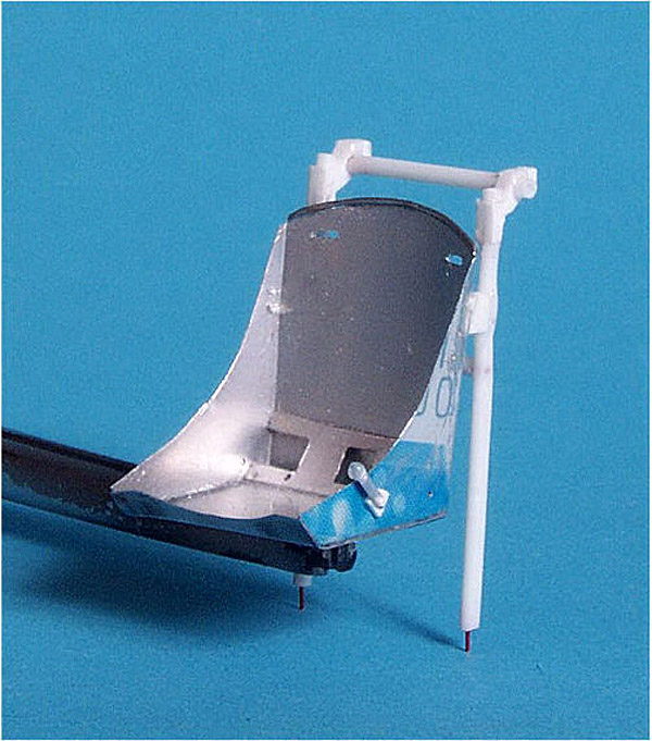
| The seat is
made from soda can aluminum. It is much closer to reality in thickness and
is, in many ways, easier to work with than styrene. I used a piece of
0.015" solder along the top to simulate where the metal was rolled. the
CA for the most part works well to bond the pieces together. I used a file
to smooth the glue seams. A sharp #11 blade works very well to cut the
aluminum. The frame was constructed of styrene sheet and rod.
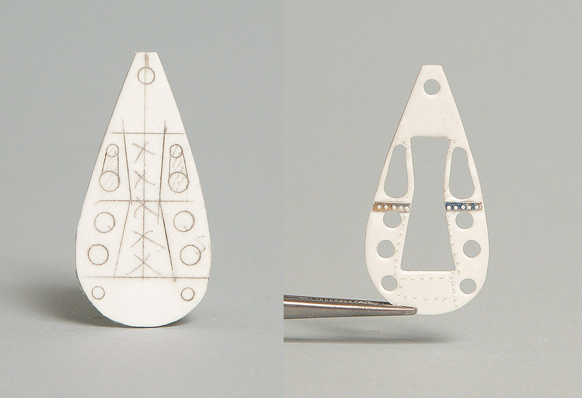
The simplest way I have found to do this is to use a 3 x 5" index card, draw out your master for this part, cut it out and transfer the pattern to the aluminum with a very sharp needle. One need only score the aluminum with a sharp #11 blade and it will break very easily upon bending. |
 |
|
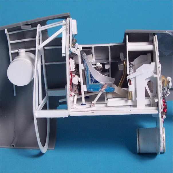
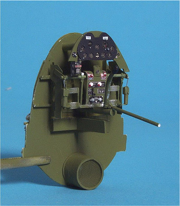
With everything finally installed
|
|
|
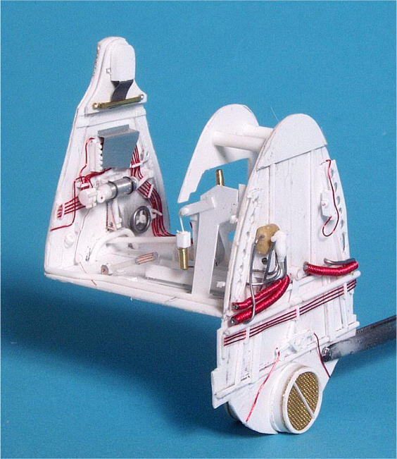
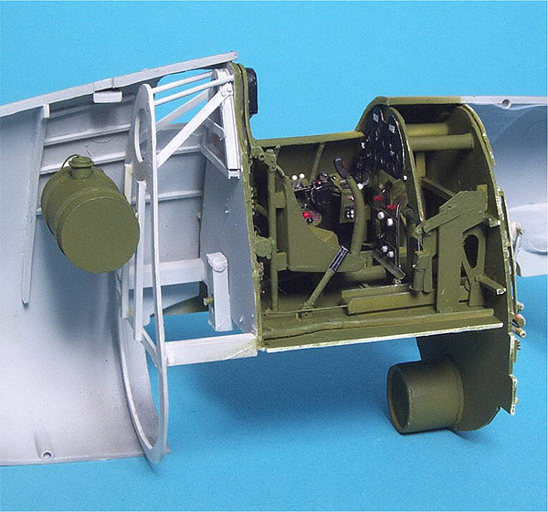
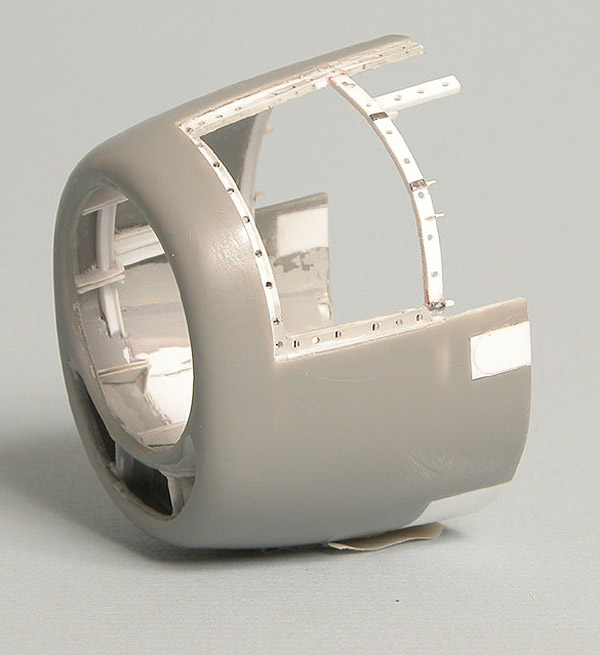
Next, the side consoles, instrument panel and other detail the rear
bulkhead was cut from styrene sheet and the fuselage fuel tank (made from
1/2" styrene tube) attached to it. Additional additional details were
added with styrene strip and rod and stringers added to the fuselage
between the ribs. I went to this level of detail as it will be visible
through the small windows directly behind the cockpit
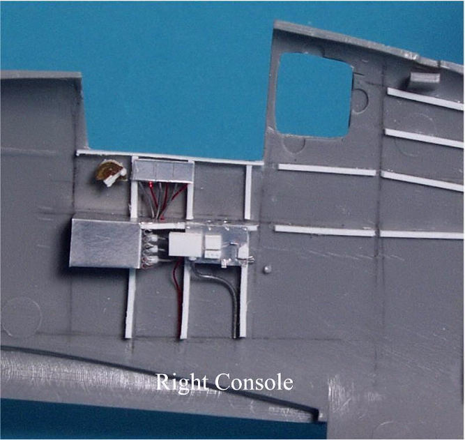
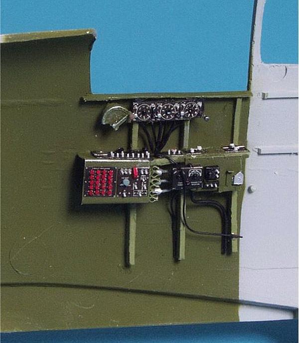
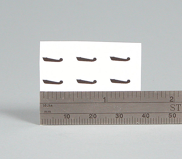
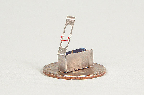
The placard set for the Hellcat, like all the other ones, goes farther to dress up the cockpit than any other single item. The details on the sidewalls are a combination of styrene, solder, lead foil, wire and soda can aluminum. The right console contained spring steel clips to hold 6 rounds of flare pistol ammo. I wrapped a thin strip of aluminum around a 0.025" drill bit, snipped it off with a pair of surgical scissors and glued it in place with CA. A minor detail but one that adds a lot to the console. |
|
|
|
|
|
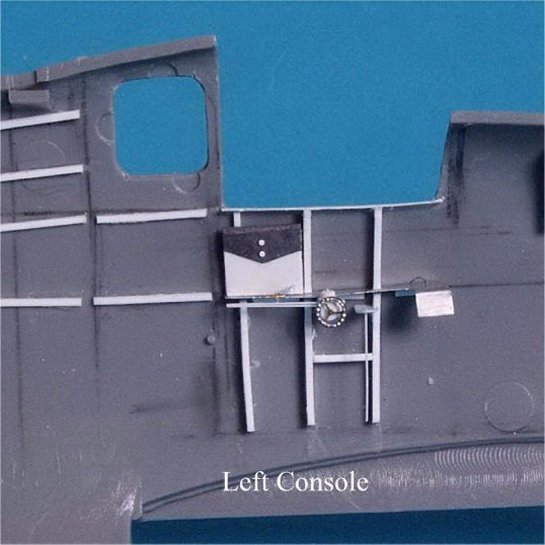
The left side with everything installed prior to finishing
|
|
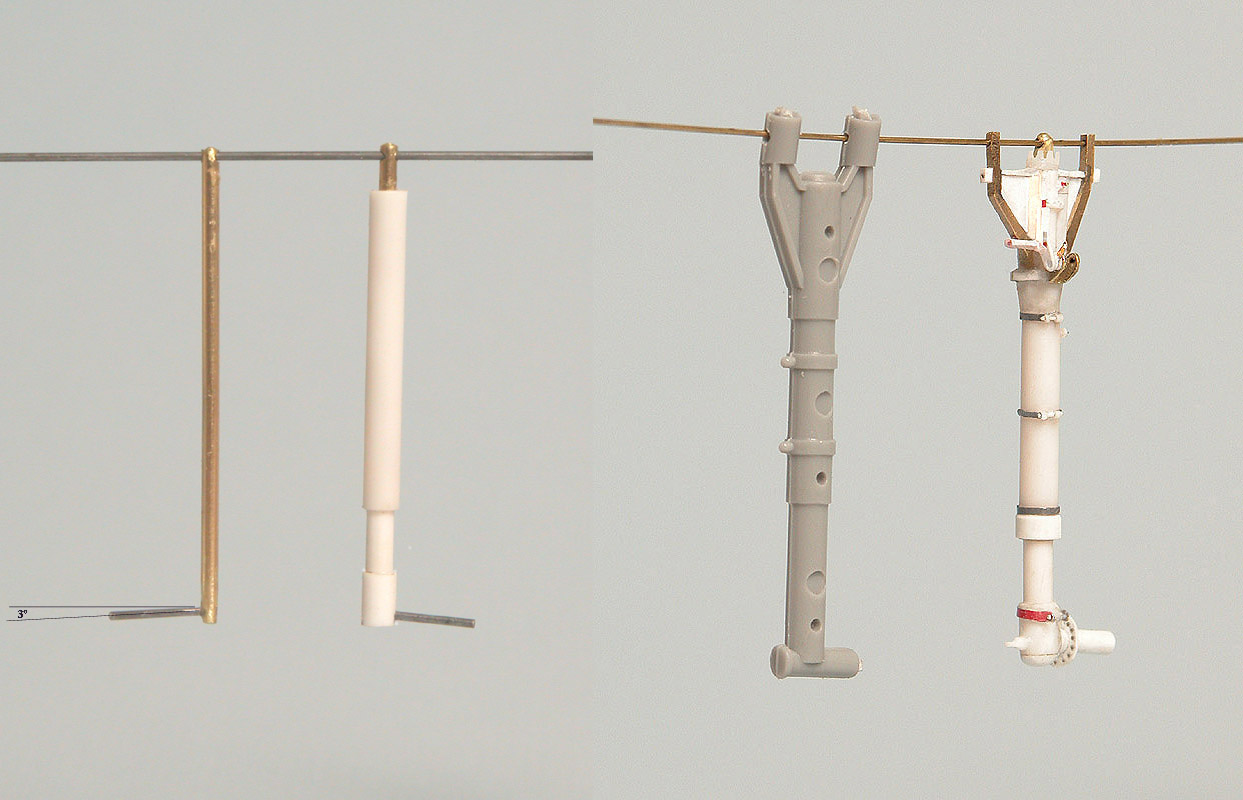
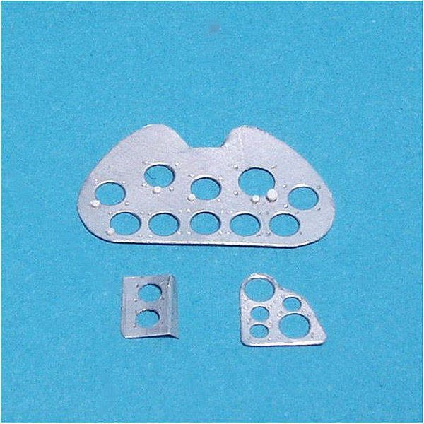
| The main and
supplemental instrument panels were cut from soda can aluminum. This is
easier to work with than styrene and has a more scale thickness effect. I
punched holes through the sheet with the Waldron punch set. The aluminum
sheet is only 0.004" so it poses no problems for the punches, just be sure
to oil them beforehand. The rivets around the instruments were added with
a #80 drill bit and the knobs are 0.018" punched disks. I will add Waldron
instruments and other small details before installation.
|
 |
|
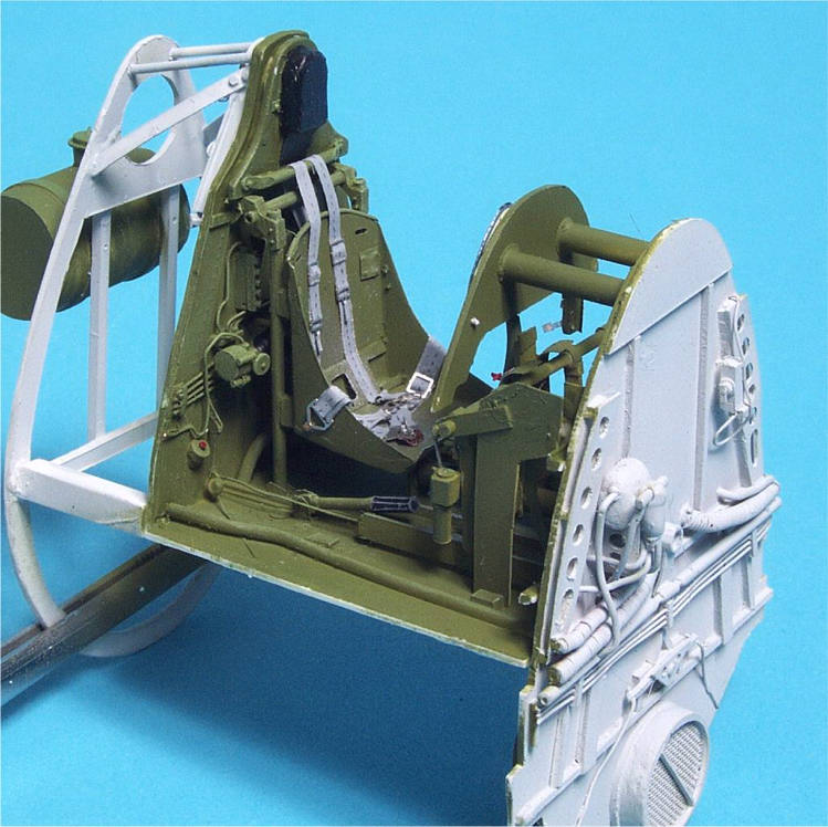
With everything constructed, it's time to paint things and add the Waldron
cockpit placards and instruments. The seatbelts are made from thermal
paper, the kind you get for a gas station receipt. It is thinner than
regular paper yet it is finer in grain and stronger. It takes paint very
well. The hardware is from Waldron.
|
|
|
|
|
|
|
|
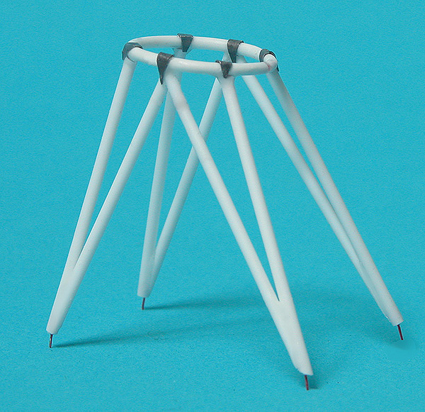
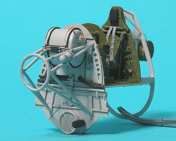
| The Engine | |
|
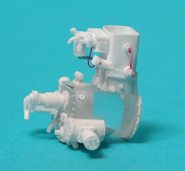
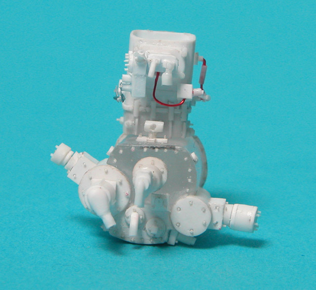
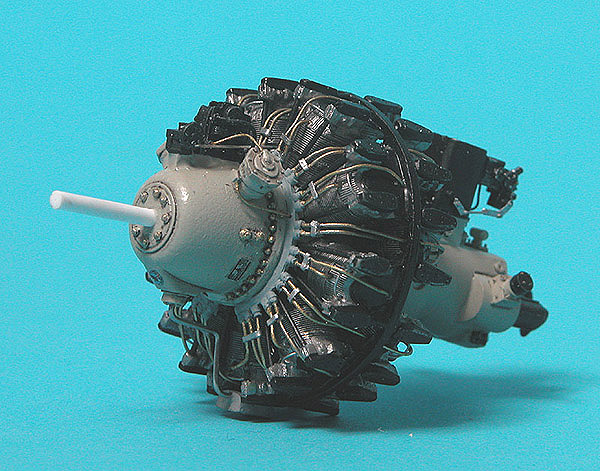
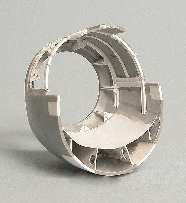
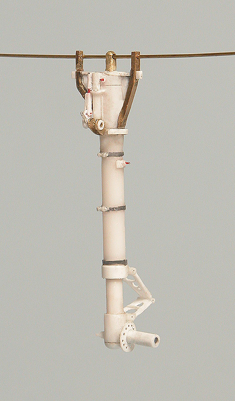
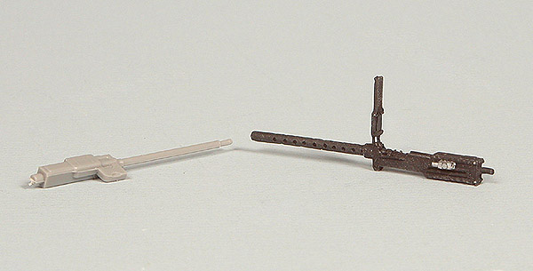
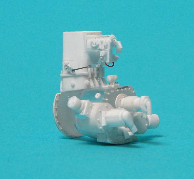
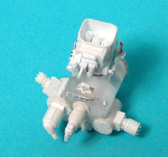
With the cockpit finally complete, it is time to turn my attention to the engine, firewall and everything in between. I decided to pitch the kit engine. The detail on the cylinders is soft and overall the detail is somewhat lacking. Plus, no detail is provided past the back edge of the crank case. As I have done on two previous 1/32 P&W R-2800 powered aircraft, I decided to replace the kit engine with the Teknics one, now marketed by Meteor. It is superbly cast and provides a great starting point for super detailing. It too, however, stops at the back of the crankcase. I started with a piece of solid acrylic rod (all I had that was the right size diameter) and added styrene rod, strip and stock to build the accessory section. The rivets are made from pieces of 0.010" rod inserted into holes and snipped off with a pair of very sharp surgical scissors. The actuators are made either from steel wire or 0.010" styrene rod. Pieces of soda can aluminum were also used. I began with the accessory section. I started with a piece of solid 1/2" acrylic rod and added all the accessories from there. They were constructed almost entirely from styrene sheet, rod and strip, along with a lot of punched discs using the Waldron punch set. I used some wire and soda can aluminum for some of the finer linkages and such. |
|
|
|
|
  |
|
|
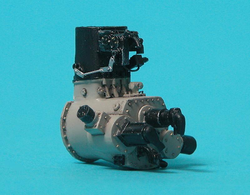
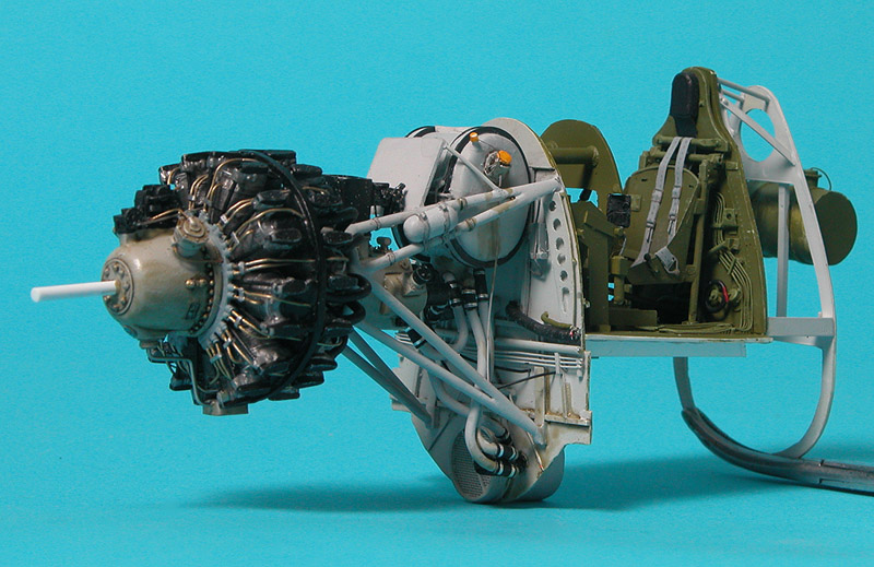
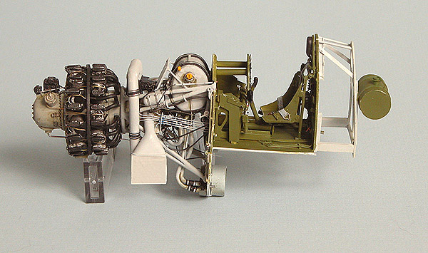
And all painted and ready to be installed on the back of the engine.
|
|
|
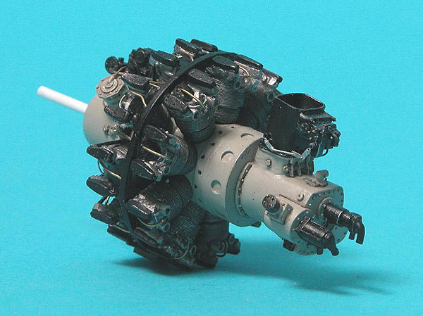
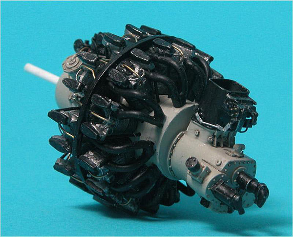
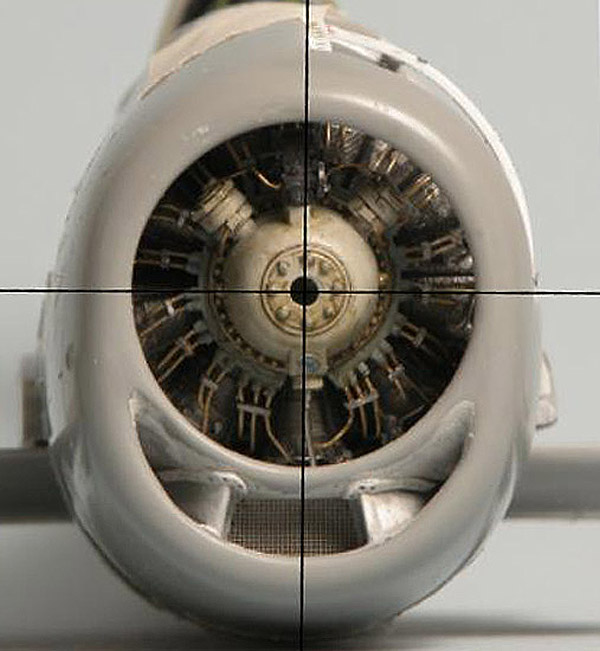
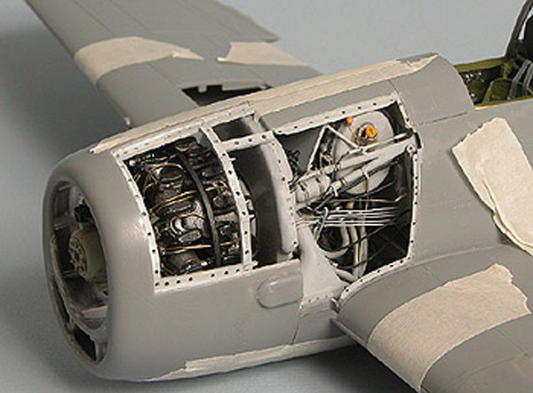
The Meteor resin Pratt and Whitney R-2800 engine is truly a kit unto itself. However, like nearly all other manufacturers, Meteor left out the ring that separates the cylinder banks. It is an integral part of the engine as it provides some structural support, attachment for the heat shields atop the cylinders and a routing area for the ignition wires. I constructed a ring from 0.040" square styrene strip. It was attached to three cylinders with a piece of styrene rod. This was actually not how it was attached but this was the simplest way to do it. The pins were hidden once the shields were in place. I made a template for the shields on MS PowerPoint and printed them on 0.005" clear styrene (yogurt lids) with the ALPS. I cut them out and attached them to the ring with CA. The thinness of the plastic made it easy to follow the contours. Once it was dried it was pressed down into the curve of the cylinder heads. A hole was drilled in the center of each so the wire going to the back cylinders had a place to go.
|
|