|
|
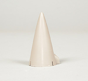
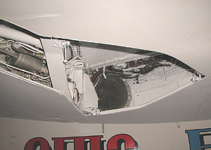
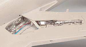
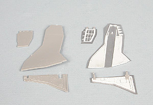
| Nose Wheel
Well |
|
|
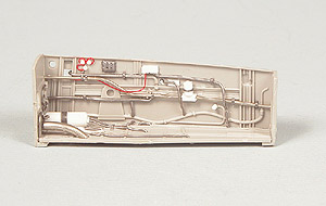
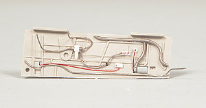
The
nosewheel well area is going to
need a lot of work. Detail is lacking and in many cases, inaccurate.
Fortunately, the nosewheel well comes in five pieces so it will be easy
to detail. Solder, wire, styrene rod, strip and sheet and lead foil rounded out the
necessary materials. Because of the way they are constructed, the mainwheel wells
will have to be detailed once they are put together. They are worse than
the nosewheel so I will pretty much wipe them slick and completely redo
them. More on them later. |
Click on thumbnails to enlarge |
|
 |
|
|
|
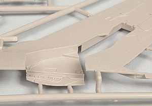
Nose Strut |
|
|
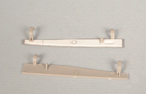
As I
previously mentioned , this is going to be a very heavy model. The
instructions call for 110 grams (3.88 oz.) of weight in the nose to
offset the tail. I think this is perhaps conservative so I will add
about 25% more above that just to be on the safe side. Subsequently,
there is going to be a lot of stress on the nose strut to support all
this weight. I got white metal main struts but could not find a metal
nose strut. I know there are some currently available but when I got the
metal ones two years ago they were not so I do not see the sense in
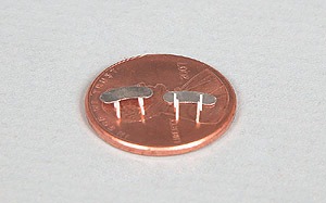
getting a whole new set just for the nose strut. To that end, I am going to beef up the kit pieces with
steel pins. I have a supply (though dwindling, admittedly) of
0.030" steel pins from an old contour gauge that are perfect for the
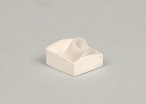
job. I first CA'd a piece of 0.125 x 0.25" styrene block (Fig. 1)
in two places to the outside of the nosewheel well sides to serve as a reinforcing
block. Overkill perhaps, but it will be more than adequately strong. It
is much better to err on the side of caution. I ground a channel into
the nose strut halves using a 0.033" carbide drill bit (Fig 2) and
bent a piece of the 0.030"wire to fit inside of it. I used liberal
amounts of CA to affix it in place and then ground any bits protruding above the channel
flush with a Dremel cut-off wheel. This will significantly
strengthen this strut at it's weakest point. Likewise, I reinforced all
attachment points for the other nose strut pieces with steel pins where they
will insert through holes drilled in the styrene reinforcing
blocks. I did not have handy any metal rod or tube of appropriate size
for the inside of the strut so I did the next best thing; I strengthened
a piece of 0.080" styrene rod with a steel pin and inserted that
into the strut (fig. 3, lower right). The pin extends past the styrene
to mate with the top half of the strut, adding rigidity to the entire
structure. This little project was good for close to two hours worth of
work however the benefits gained far outweigh the time required. This
strut will not break or deform under load for any foreseeable amount of
time. |
Click on thumbnails to enlarge
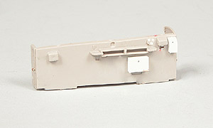
Fig. 1 |
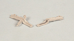
Fig 2 |
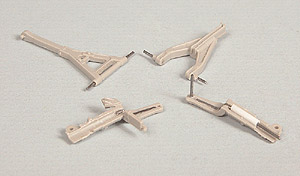
Fig. 3 |
|
|
|
|
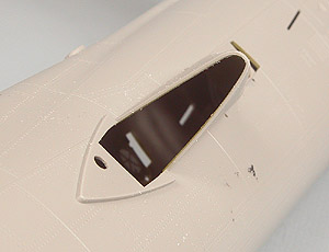
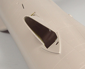
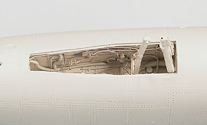
| Radome |
|
|
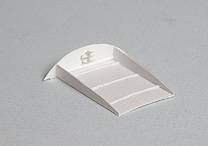
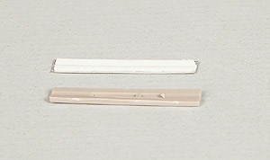
Trumpeter,
like pretty much everyone that has ever produced a THUD kit, got
the contours of the radome off by a good amount. When placed against a
scaled up photo of the real thing, the kit piece is too long
and way too "pointy". There is a definite curve to the tip of
it. The kit piece looks like something that should be
on the front of a Delta Dagger instead of a Thunderchief. I used the razor saw and cut off the top
4mm or so and reshaped it using the Dremel and a grinding bit, files and
sandpaper. Fortunately the tip of the radome was of sufficiently
thick plastic that I did not have to add any styrene, just some CA at
the very tip. The difference is very noticeable. The tail and rudder
have some pretty sizeable shape issues as well and will have to be dealt
with in time. That is going to be a considerably bigger undertaking than
the radome! |
Click on thumbnails to enlarge
 |
|
|
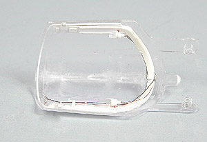
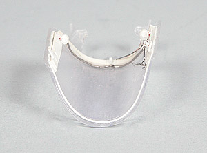
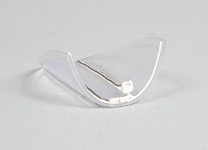
| Canopy and
Windscreen |
|
|
I am not
following any specific order as this time, just whatever interests me at
the time. Like the rest of the kit, the clear parts are very large.
Quality is not as good as I would expect from a kit in this price range
but it's acceptable. Areas of the canopy and
windscreen that would be occupied by framework are lightly frosted,
which makes it easier to distinguish demarcation lines. The windscreen
had a scratch that ran along the inside of it so I had to polish it out,
no biggie. As soon as I removed the
canopy from the sprues I noticed something that I have never seen in all
my years of modeling.....THERE WERE FINGERPRINTS ON THE CLEAR PART! I
was floored. Fortunately the oils and acids on that person's fingers had
not etched into the plastic. I cleaned them off with detergent and water
and coated them with Future™. Both the canopy and windscreen were
totally void of any details. Since there was a fair amount of structure
on both, the canopy especially, I constructed it from reference photos
using styrene, solder, wire and soda can aluminum. All in all I added
about 40 pieces to the canopy. I added a control box and wet compass to
the windscreen along with a few bits of styrene for framing details. I
will insert a Waldron instrument in the wet compass when it's been
painted. |
 |
 |
 |
|
 |
|
The kit did not
come with any mirrors for the front canopy bow (there are two) so I cut
some out of soda can aluminum, removed the paint on one side (leaving
the plastic coating on the other because CA adheres to it a lot better
than to the bare metal), with 0000 steel wool and then polished it with
the Dremel and some Turtle Wax Clearcoat polish. I may glue some
aluminum foil onto them after they are painted as that will give as
close to a mirror finish as you can get. Polished aluminum is pretty
shiny but aluminum foil is better. I made the attachment points out
of some 0.010" x 0.020" styrene strip. They will be
attached to the windscreen right before it is installed because they are
very fragile! |
|
|
Drag
Chute Compartment |
|
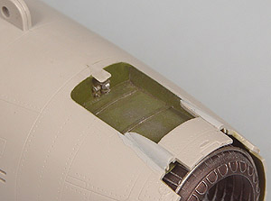
I found several
photos of THUDS sitting on the ramp or in revetments with their drag
chute doors open so I decided to leave mine open too. If nothing else it
adds a little bit of interest to the tail section. Trumpeter allows the
option and does a pretty decent job doing the door. Where they fell
short, by a country mile short, is they did not close off the
bay. If you leave it open you will be looking at the top of the engine,
which simply did not happen. No way you could lay a nylon parachute on
top of the afterburning section of an engine. I used a contour gauge to
get the shape of the interior and built a box to go around the opening.
I only had one photo of the insides of it so I did the best I could.
Raised rivets were made by turning the styrene over and running a ponce
wheel over it to make raised impressions. Simple but effective. When
all is said and finished, the improvement was well worth the effort. |
 |
|
 |
|
|
At
this point I have joined the fuselage halves. Fit between the halves
for the most part was very good. Not a lot of seam cleanup is going to
be required. A fair amount of touch-up rescribing will be required
because this model has a lot of panel lines. Next up is to address the
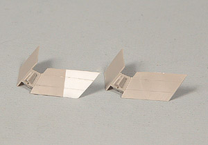
incorrect shape of the vertical tail. |
|
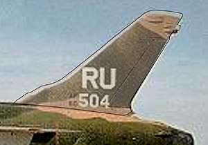
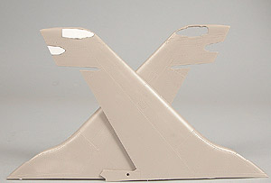
Much has been
said about the shape of the Trumpeter tail. Before I took the razor saw
to it I searched the web for a good while to find a photo of a THUD from
an exact side plan form view. I finally found one. I photographed the
kit tail, still on the sprue (though I taped the rudder in place) and
cut it out in Photoshop. I outlined it with a fine black line and
increased it's transparency. I then superimposed it over the photo of
the real thing. I immediately noticed that the kit tail was too tall and
that the ECM fairings were in the wrong place. Any slight differences in shot angle of the two photos would not
account for the height and location differences. Lowering the top of the
tail will be a pretty easy task. Moving the ECM antenna fairings are going to take a lot more work. The first thing I did was to cut out
the four ECM fairings with a #80 carbide drill bit in my battery
operated Dremel (because it turns at a slower speed than the lowest
setting on my AC one), using great care not
to break it. They are so sharp that they really work the best for
cutting out small parts. I then cut pieces of 0.030" thick styrene sheet
using the holes as templates and filled them in, using CA to fill any gaps. The pieces
were then sanded
smooth with files and sandpaper and polished with 0000 steel wool. Next
up was to take the razor saw and remove the top .18' or so from the tail
and reshape the top contour to match the photo. The thin black
line in the photo at right delineates the new top of the left piece compared to the original
right piece. From a distance you can see how much of a difference there
is. The top of the fin was filled with CA and the ECM antenna fairings
replaced in their correct locations. |
 |
 |
 |
|
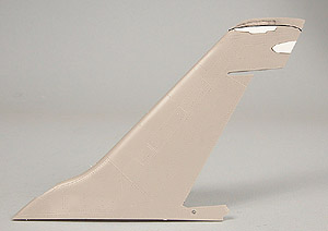
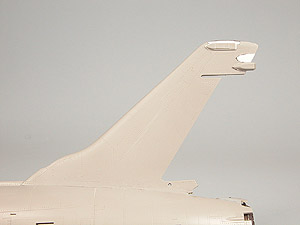
| With the tail
modifications finally completed, it becomes apparent how far off the kit pieces
were, the lower antenna especially.
Was it worth 4 hours of work to correct it? Most
people might say no but I figured if I am going to correct
other glaring errors in this model (the radome and drag chute
compartment to name two) I may as well do all of them. I know there
is a resin replacement for this fin but why plunk down a bunch of money
for someone else's work when I can do it myself and get the same
results? |
 |
|
|
Combat
Camera |
| The kit includes
the fairing just behind the radome for the combat camera but once again
there is nothing inside, leaving yet another Trumpeter signature black
hole. I constructed a box out of sheet styrene and made a lens out of
styrene tube and clear sprue. In this scale it would be noticeable that
there is nothing behind the "glass". |
 |
|
|
At
this point it is time to attach the wings to the fuselage. I plan on
leaving the flaps and slats down but will probably just glue them in
place. The hinges included in the kit do not appear to be very strong.
Once the wings are on I can start detailing the main wheel wells. |
|
|
Wings |
|
Before
I could start putting the wings together I had to accomplish several
tasks. First off was to fill in several very large (0.20") ejector
pin marks in the intakes. 500 pound bombs don't make holes that big and
I should know, I have dropped my fair share of them. One was actually
raised for half of it and sunk for the other half. This is totally
unacceptable for a kit of any price, much less one that costs a
C-note or more. Additionally, there is a rather pronounced (0.050")
step on the fuselage intake area that lies barely 1/2" inside the
intake. Granted, I may not have any photos of the inside of a THUD
intake but I would be willing to bet my next paycheck that this step is
not there in the real thing. And they would be very visible in the
completed model if not corrected. The easy way out would be just to make
FOD covers for the intakes but I want them open. I took the Dremel and a
grinding bit and ground away the step, tapering it to a knife edge so it
would not be noticeable once the wings are in place. When the wings and
fuselage are joined it will give the impression of a continuous surface. |
 |
|
 |
|
Wing
construction was fairly straightforward, to a point. Trumpeter provided
two separate sprues for the port and starboard wings. (Western?) logic
would dictate that ailerons, flaps, slats and spoilers on one sprue
would mate with the corresponding wing halves on that sprue. As
the inimitable John Belushi (aka "Bluto" from Animal House) would have said
"But nooooooo!". Ailerons, flaps, slats and spoilers
for one wing are found on the sprue for the other wing and vice
versa. I am still shaking my head in bewilderment over that one.
It left me wondering what Confucius would have had to say about that
one; perhaps "Sum Ting Wong!". They do provide
some metal rods and PE parts so you can make the flaps and slats
positionable. At a quick glance, they did not appear to me to be
particularly substantial and I was right. Mounting the flaps was
straightforward, however trying to mount the slats was an exercise in
utter frustration. I finally glued the wings together without them and
will mount the slats once everything is dry and I clean up the awful seam
that runs down the area directly behind it. The kit also provides separate
spoilers so they can be positioned either up or down. The only time
spoilers would be extended is if the aircraft were on rollout (to
shorten landing distance) or maintenance was being performed on them.
Therefore I decided to display them in the stowed position. The fit was
less than perfect, a seemingly all too frequent occurrence with this model,
necessitating that each piece be individually fitted. Another
unnecessary time waster. There was also a pretty nasty seam on the
inside of the intake when the wings were joined but some filling with CA
and filing and sanding . The fact that the area is easily
accessible before the wings are joined to the fuselage made this an easy
task. |
|
|
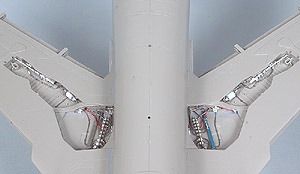
Main
Wheel Wells |
|
The
detail in the mainwheel wells is, to put it tactfully, well.....awful.
It is fictitious in most places and very sparse to non-existent in
others. As you can see from the photos at right, Trumpeter's rendition
falls woefully short of the mark. They also leave a black hole in
the wheel wheel where that grayish electric motor (which they also left
out) is in the photo so that will also have to be corrected with a
bulkhead. THUD wheel wells, like most modern jets, are a pretty busy
places filled with wires, cables, actuators, hydraulic and oil lines,
etc. I did not take me more than a millisecond's worth of pondering that
there really was nothing in these wheel wells worth saving so I took the
Dremel and a grinding bit and wiped everything slick. I will just go
ahead and scratch build all of it. I do believe someone makes a set of
resin wheel well inserts for this model. Unless you are a glutton for
scratchbuilding punishment like I am, I would strongly suggest you
invest in them. In this scale, there is no excuse for the really weak
representation presented by these wheel wells. The scratchbuilt wheel
wells are constructed of wire, solder, soda can aluminum, stainless
steel screening, lead foil, styrene sheet, rod, tube and strip. I added
a soda can insert to one side of the wheel well so I could add raised
rivets. It is easy to work and if you glue the side that has the plastic
liner to the styrene it adheres very tightly with some CA. It took about
14 hours to complete this one well but the finished results were
definitely worth the effort. |
The Real Thing
 |
|
Trumpeter's rendition
 |
|
Completely
reworked
|
 |
|
|
 |
|
 |
|
|
|
Main
Landing
Gear Doors |
|
The landing gear
doors are going to also need to be re-done. They are very thick and, in
the case of the main doors, totally void of detail. Since I was working
from essentially nothing, good planning was a must. I traced the kit
piece onto a piece of 3" x 5" index card and then drew in all
the detail. I then cut out the pieces of the card and traced them onto
the sheet styrene with a pencil and cut them out with a fresh #11 blade.
I also used the kit
pieces as templates and cut out new pieces from soda can aluminum. The
only thing I will save from the kit doors are the hinges. I added
styrene sheet to the aluminum to build up the center parts of the doors.
As the
photos at right show, the difference is quite noticeable. Once again,
for an aircraft in this scale, Trumpeter should have done a considerably
better job than they did. |
 |
|
|
Nose
Landing
Gear Doors |
|
As
bad as the main landing gear doors were, they did not even approach the
nose gear doors. I got irritated at the main doors, I got downright furious
at the nose doors. Not only were they very thick and totally lacking in
detail, they were covered in four nasty ejector pin marks. I have
seen 1/72 and even 1/144 parts that were far better done this. For 1/32
it's totally unacceptable. Once again I traced the outline onto soda can
aluminum and added sheet styrene to form the inner body of the door.
Like the mains, I kept the kit hinges but that was it. The rest are
destined for the trash where they belong. |
 |
|
|
Odds
and Ends |
|
There are a few
other things that need attention before I start on the external stores
and ordnance. First up was the doors for the inflight refueling probe. Like all the other doors
in this kit, they were extremely thick and completely devoid of detail. I
once again
traced the outline of the door on soda can aluminum and cut out some
sheet styrene for the center of the door. I used a file to make a groove
down the middle of the door where it will mate with the probe. There is
a second door, forward of the main one, that closed after the probe was
extended. All that needed to be done on that one was thin the edge that
would be visible, no point in doing more work than is necessary. |
 |
|
|
Jets have numerous
drains along the underside of the fuselage, especially around the
engine. Using reference photos, I drilled several 0.027" holes and
inserted pieces of 0.025" rod with a 0.0135" hole drilled in
the end. The fuel dump mast had a basically solid end to it so I drilled
it out and inserted four pieces of 0.010" wire through the side of
it. Sometimes it's the little details! |
 |
|
|
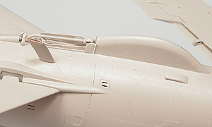
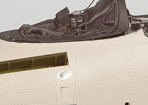
There is a large
vent on the port side of the fuselage just below and aft of the inflight
refueling probe bay. In the model it is simply depicted as an oval
depression. On the real thing there is a definite hole there. I ground
out the oval with a Dremel and grinding bit and inserted a piece of
styrene tube into the hole. I thinned the edges to near scale thickness
with a round file. I also ground out the cooling slots in the door
covering the M-61 20mm Gatling gun with a 0.020" carbide drill
bit. As you can see from this photo, there is a gap between the
resin coaming and the kit piece. I filled it in with some strip styrene
as it will be noticeable. |
 |
|
|
External
Stores and Ordnance |
|
The first thing I
noticed when I started looking at the external fuel tanks and armament
was part of one of the drop tank fins had been torn in half. It was not
in the bag so I had to fix it with some styrene sheet. Unlike so many
models that depict fins on drop tanks as thick, rectangular cross
section slabs, Trumpeter actually made these very thin and tapered, a
nice touch. I cut off the bad part of the fin with a Dremel circular saw
and added a piece of 0.025" styrene sheet, adding the taper with a
Dremel shaping bit and files. A little bit of rescribing and all fixed!
The rest of the drops went together well but a fair amount of filling
with CA was required where these fin sections fit into the tank
itself.
I made up six M117 750lb GP bombs and two Mk82 500 lb
GP bombs. The fuses supplied with the kit were somewhat crude so I
reworked them, adding some soda can aluminum to simulate the spinner
blades.
|
 |
|
|
General
Construction |
|
For the most part
the kit went together reasonably well. Fit was excellent in places and
pretty poor in others. The windscreen fit rather poorly, requiring a lot
of filling, filing and sanding. Trumpeter's system for attaching the
slats was totally inadequate. In addition to being very weak, it was
also very inaccurate. Trumpeter's system for the flaps and slats was
fragile, and in the case of the slats, fictional. I decided to just glue
them in place in the up position. I drilled holes in the top
of the metal landing gear and inserted a 0.030" steel pin. I then
drilled a hole all the way through the wing where the strut was
attached. I cut off the pin and grounded the area flush with the wing.
The struts themselves were affixed with a liberal amount of CA and the
pin added a good bit of rigidity. I don't anticipate any problems with
either the main or nose gears. |
|
|
Painting |
|
I sprayed the model
and the myriad number of free parts with automotive primer out of a rattle can. The sheer
size of this model pretty much makes this a necessity. I painted the
model in the standard four color SEA (Southeast Asia) pattern of FS
36622 camouflage gray) for the undersides and FS30219 (tan), FS34079
(dark green) and FS34102 (medium green) for the upper surfaces. Bombs
were painted FS34079. Painting something this large was quite an
undertaking; the process took me about five hours to complete. Once the
enamels were dry I sprayed the model with two coats of Future™ to
prepare it for decaling. |
|
| |
|
Decaling |
|
The decals
supplied with the kit are designed by Two Bobs and printed by
MicroScale. They are gorgeous so I saw no need to look elsewhere or make
any for myself on the ALPs. They went down very easily and once dry the
carrier film was all but non-detectable it was so thin. |
|
|
| |
|
This build was profiled in FineScale Modeler Magazine. |
|